
 中文
中文 021-6525 3206
Ultra-high vacuum sample grabbing method
This introduction mainly focuses on the most widely used type of sample holder in the field of surface analysis: Flag Type Sample Holder (Chinese name: Flag Type Sample Holder)

Technical Support
 Your current location: Home > Technical Support > Practical explanation/FAQ > DC Temperature ...
 Q:C/KThe temperature setting of the thermostat is capped and the software cannot set it. How can I modify it if I want to set a higher temperature?
A:CType thermostat factory default range:0~2320℃;KType thermostat factory default range:-200~1372℃
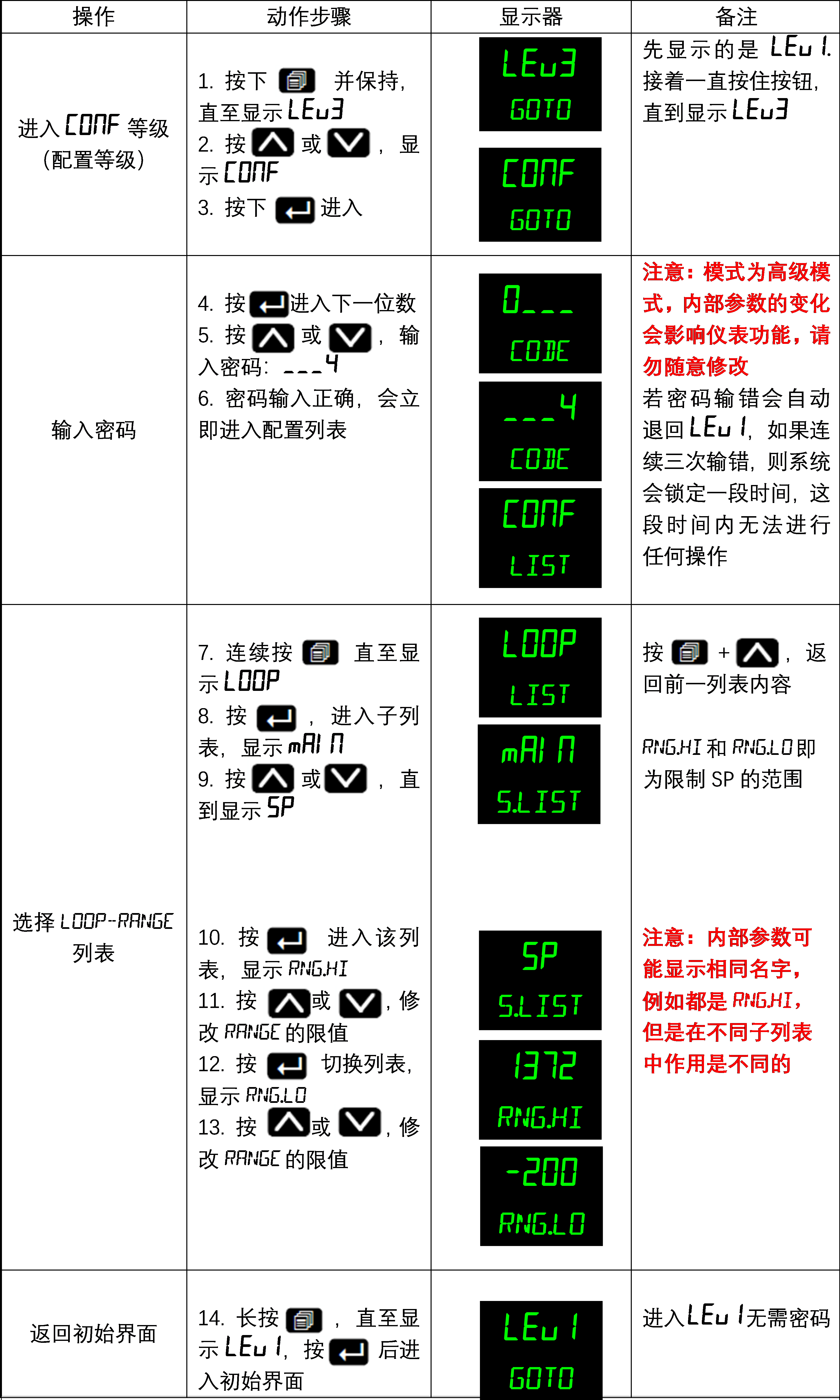
Fermi_mTC software only modifies the upper and lower limits of SP. In fact, there is also a RANGE parameter in the thermostat to limit the range of SP.
3216 thermostat automatically switches to the corresponding temperature range after setting the thermocouple type due to hardware limitations and cannot over-adjust its range.
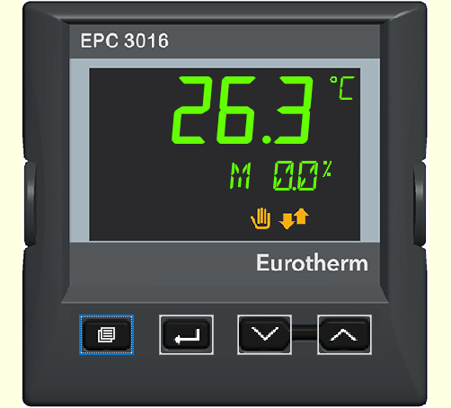
3016 thermostat is an upgraded version of 3216 thermostat. It has been upgraded in hardware and can therefore over-adjust the temperature range. However, the adjustment of temperature parameters may affect the working life and working status of the equipment. Users need to evaluate and bear the risks and possible losses caused by the adjustment of underlying parameters.
Steps:
Q: When the software Fermi_mTCcommunicates with the thermostat, the software interface will trigger ALARM? But there is no alarm information on the front panel of the thermostat and the output is normal, and the temperature rise has no effect!
A: By default, the thermostat panel is pressed at the same time  and
and  (the first and second buttons from left to right on the panel), is used to confirm the alarm and eliminate ALARM (only limited to clearing the problem ALARM). If the PV row indicator light on the front panel of the thermostat is red and scrolling information is displayed, it must have triggered an alarm event. The steps to eliminate this type of alarm are answered as an independent question.
Q:Thermostat andFermi_mTCsoftware cannot communicate?
A:Try to solve it by the following methods:
Method1:Please check if the parameters are correct?
1Check whether the correct RS485communication cable is used and whether the connection is normal;
2)Confirm whether the COM port is selected correctly;
3)Check the communication parameters. Currently, there are multiple versions of the communication parameters of the thermostats sold by our company.
Early version 3216 Thermostat baud rate: 19200/9600 Address: 1
Later unified 3216,3016,3004 Thermostat baud rate: 9600 Address: 2
Method2: Possible computer<spanthe com="" port="" is="" occupied="" and="" needs="" to="" be="" released.="" restart="" the="" computer.="" <="" p="">
Q: The DC power supply of the early version of the temperature controller has no output?
A:Note that the following operations need to be performed by personnel with circuit maintenance experience, otherwise it may cause personal or property losses. All wiring terminals and hardware changes must be performed under power-off conditions.
This problem requires the elimination method, first eliminate whether there is a problem with the DC power supply, and then eliminate whether there is a problem with the thermostat.
Mode 1 (Local mode):
The DC power supply is normally connected to the load. First, switch the DC power supply to the Local mode. As shown in the figure, connect the rear panel terminals 5 and 6 short-circuit, manually adjust the DC power supply front panel knob (it is recommended to adjust the value to a smaller value) and press out to output and check whether it can output normally! If the display is still 0, please contact after-sales!
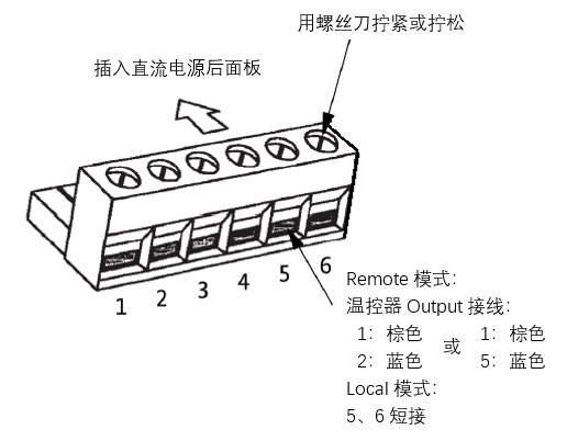
Mode2 (Remote mode):
Check behind the thermostat<span is="" the="" output="" line="" and="" dc="" power="" supply="" wired="" correctly?="" there="" any="" skin="" compression?=""
The early version of the DC power supply Output wiring is 1 brown5 blue, and the later version is 1 brown2 blue. If there is a pin definition label next to the terminal, follow the label. If not, you can try both wiring methods, and then use the thermostat to increase the temperature to check whether the DC power supply has output!
Method3:
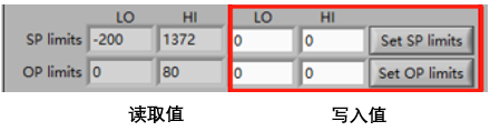
Check if the internal parameterOP.H of the thermostat is set to0?
OP.HI refers to the output upper limit, output range: OP.LO~OP.HI, if the output upper limit is set to 0, it will result in no output
You can view and modify OP
limits
Mode 2 and mode 3Cannot solve this problem, please contact after-sales!
Q:Thermostat front panel alarm information:S.brk ?
A:ThermostatPVrow displays S.brk,SVrow scrolls with IN
PUT SENSOR BROKEN information.
Please check:
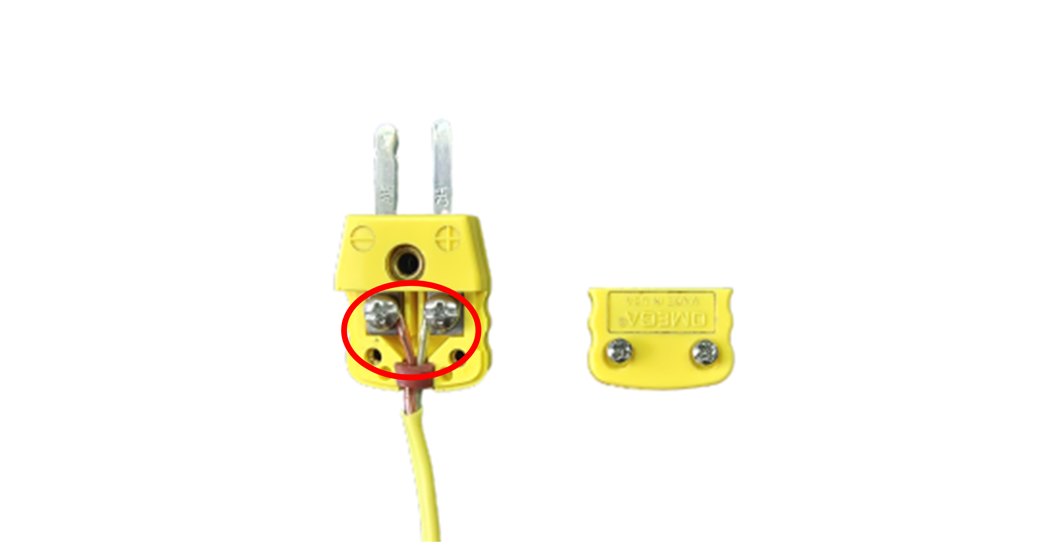
1) Is the sensor (thermocouple) correctly inserted?
2) If the sensor (thermocouple) is short-circuited, open the thermocouple plug if necessary to check whether the wiring is normal and whether there is any loose connection.
Q:Thermostat front panel alarm information:S.RNG/O.RNGorS.RNG/u.RNGAlternate display
A:ThermostatPVline displays S.RNG/O.RNG or S.RNG/u.RNG alternately,SVline scrolls with INPUT
SENSOR OUT OF RANGE information.
Indicates that a sensor is out of range, and the PV input value exceeds the input range5%, an alarm message will be displayed.
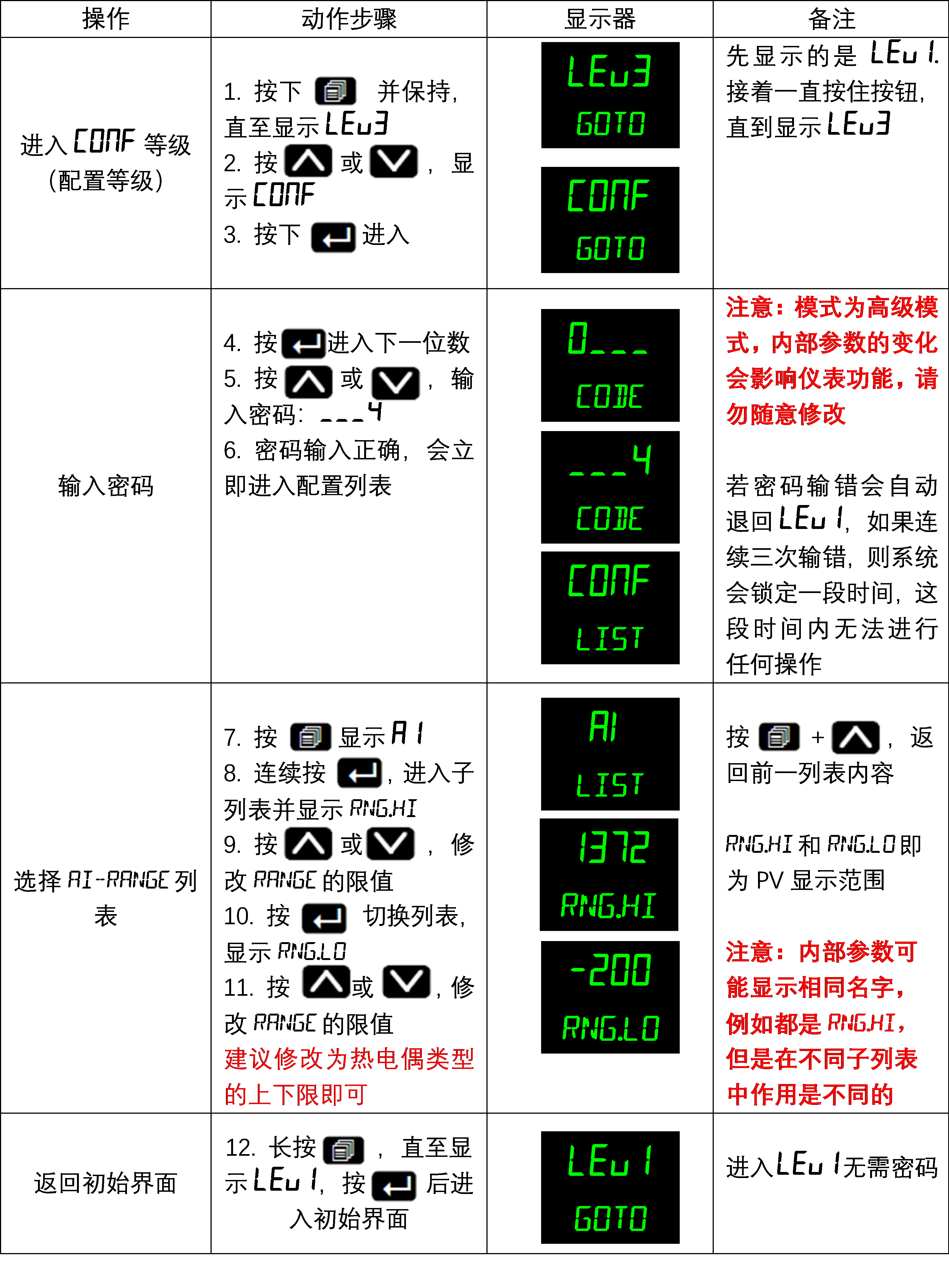
There is a RANGE parameter in the thermostat parameters that limits the display value of PV. Once the temperature read exceeds the range of this value, HMI will alarm. S.RNG/O.RNG indicates that the upper limit is exceeded, and S.RNG/u.RNG indicates that the lower limit is exceeded. It is recommended to modify it to the upper and lower limits of the thermocouple type.
Modification steps:
Q:Thermostat front panel alarm information:P.CnF
A:When the thermostat is turned on, the PVline displays red P.CnF,SVline is accompanied by POWERED
DOWN WHILST IN CONFIG MODE
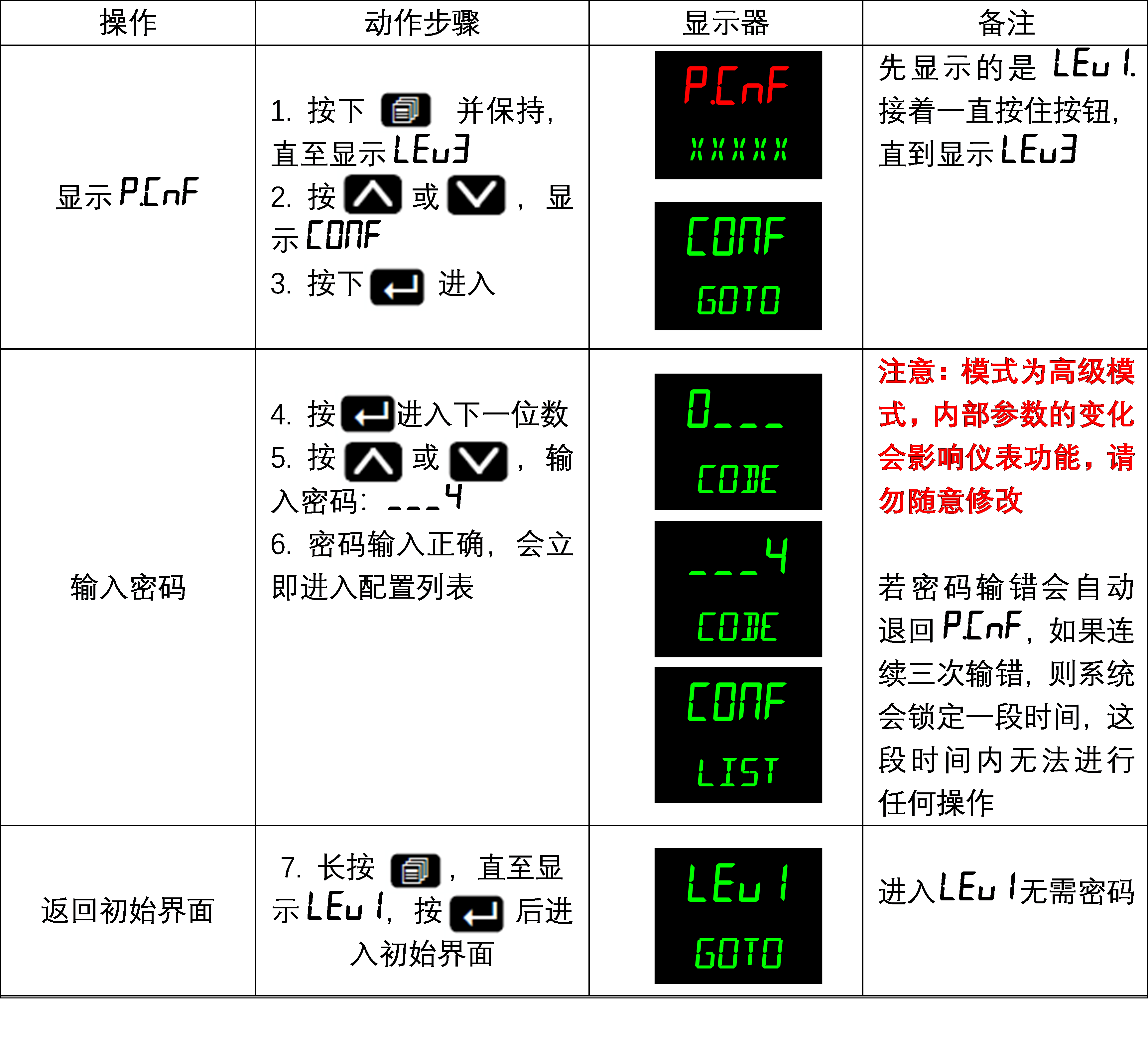
The thermostat loses power in the configuration mode. If the configuration mode is not exited correctly, the alarm message will be displayed the next time the thermostat is turned on.
You need to exit correctly again to eliminate this alarm.
Steps:
<span q:="" the="" displayed="" value="" of="" thermostat="" pv="" fluctuates="" greatly?="" <="" span="">
A:Most of the reasons are caused by not setting the correctPIDparameters.
PID operation includes proportional P, integral I, and differential D functions. When PID intervenes, when PV>SV, it only represents that the proportional function part closes the output. The differential mainly looks at the current temperature change trend to make adjustments and eliminate the steady-state temperature difference; while the integral is the accumulation of past history, predicts the error, and quickly responds to approach the set temperature. Therefore, even if the heating control PV>SV, there may be output, because the system believes that this is the only way to avoid excessive decrease of PV. If PV is continuously greater than SV, it is likely caused by improper PID parameter settings; it may also be caused by hardware damage.
Example of setting the temperature to 100℃ PID intervention:
P control: The temperature controller stops when it reaches more than 90 degrees (such as 96) or more than 100 degrees (such as 106) at a certain heating rate.
PI control: The temperature controller continues to increase the temperature to 96℃ at a certain heating rate, and then increases to 106℃ and then decreases back, floating back and forth around 100℃, and finally stops at 100℃.
PD control: The temperature controller rises to 96℃ at a certain heating rate, and then slowly approaches 100℃.
PID parameters are low-level control parameters. Improperly adjusted PID parameters may cause excessive power, excessive temperature rise, etc., which will directly affect the use and life of the equipment. It is recommended that the adjustment of PID parameters be carried out under the guidance of experienced engineers.


